- 8.3.1.2 Packet Tracer
- 8.4.1.2 Packet Tracer Skills Integration
- Packet Tracer Skills Integration Challenge
- 8.3.1.2 Packet Tracer Answers
Last Updated on April 29, 2018 by
8.3.1.2 Packet Tracer - Skills Integration Challenge Instructions 6ngewgjr72lv. Download & View 8.3.1.2 Packet Tracer - Skills Integration Challenge Instructions as PDF for free. 8.3.1.2 Packet Tracer - CCNA Skills Integration Challenge. From year to year, Cisco has updated many versions with difference questions. The latest version is version 6.0 in 2018. Note: The ppp pap sent-username is not graded by Packet Tracer. However, it must be configured before the link will come up between HQ and NewB.
8.3.1.2 Packet Tracer – CCNA Skills Integration Challenge
Packet Tracer – CCNA Skills Integration Challenge
Answer Note: Red font color or gray highlights indicate text that appears in the Answer copy only.
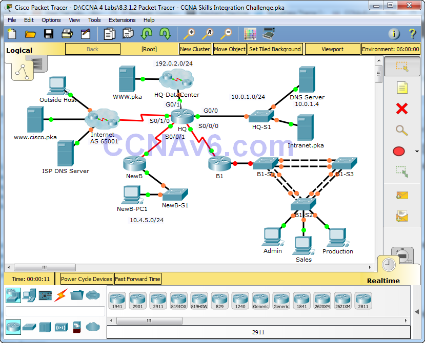
Topology
8.3.1.2 Packet Tracer – CCNA Skills Integration Challenge
Addressing Table
| Device | Interface | IP Address | Subnet Mask |
| HQ | G0/0 | 10.0.1.1 | 255.255.255.0 |
| G0/1 | 192.0.2.1 | 255.255.255.0 | |
| S0/0/0 | 10.255.255.1 | 255.255.255.252 | |
| S0/0/1 | 10.255.255.253 | 255.255.255.252 | |
| S0/1/0 | 209.165.201.1 | 255.255.255.252 | |
| B1 | G0/0.10 | 10.1.10.1 | 255.255.255.0 |
| G0/0.20 | 10.1.20.1 | 255.255.255.0 | |
| G0/0.30 | 10.1.30.1 | 255.255.255.0 | |
| G0/0.99 | 10.1.99.1 | 255.255.255.0 | |
| S0/0/0 | 10.255.255.2 | 255.255.255.252 | |
| B1-S2 | VLAN 99 | 10.1.99.22 | 255.255.255.0 |
VLAN Configurations and Port Mappings
| VLAN Number | Network Address | VLAN Name | Port Mappings |
| 10 | 10.1.10.0/24 | Admin | F0/6 |
| 20 | 10.1.20.0/24 | Sales | F0/11 |
| 30 | 10.1.30.0/24 | Production | F0/16 |
| 99 | 10.1.99.0/24 | Mgmt&Native | F0/1-4 |
| 999 | N/A | BlackHole | Unused Ports |
Scenario

In this comprehensive CCNA skills activity, the XYZ Corporation uses a combination of eBGP and PPP for WAN connections. Other technologies include NAT, DHCP, static and default routing, EIGRP for IPv4, inter-VLAN routing, and VLAN configurations. Security configurations include SSH, port security, switch security, and ACLs.
Note: Only HQ, B1, B1-S2, and the PCs are accessible. The user EXEC password is cisco and the privileged EXEC password is class.
Requirements
PPP
- Configure the WAN link from HQ to the Internet using PPP encapsulation and CHAP authentication.
- Create a user ISP with the password of cisco.
- Configure the WAN link from HQ to NewB using PPP encapsulation and PAP authentication.
- Create a user NewB with the password of cisco.
Note: The ppp pap sent-username is not graded by Packet Tracer. However, it must be configured before the link will come up between HQ and NewB.
8.3.1.2 Packet Tracer
eBGP
- Configure eBGP between HQ and the Internet.
- HQ belongs to AS 65000.
- The IP address for the BGP router in the Internet cloud is 209.165.201.2.
- Advertise the 192.0.2.0/24 network to the Internet.
NAT
- Configure dynamic NAT on HQ
- Allow all addresses for the 10.0.0.0/8 address space to be translated using a standard access list named NAT.
- XYZ Corporation owns the 209.165.200.240/29 address space. The pool, HQ, uses addresses .241 to .245 with a /29 mask. Bind the NAT ACL to the pool HQ. Configure PAT.
- The connections to the Internet and HQ-DataCenter are outside XYZ Corporation.
Inter-VLAN Routing
- Configure B1 for inter-VLAN routing.
- Using the addressing table for branch routers, configure and activate the LAN interface for inter-VLAN routing. VLAN 99 is the native VLAN.
8.4.1.2 Packet Tracer Skills Integration
Static and Default Routing
- Configure HQ with a static route to the NewB LAN. Use the exit interface as an argument.
- Configure B1 with a default route to HQ. Use the next-hop IP address as an argument.
EIGRP Routing
- Configure and optimize HQ and B1 with EIGRP routing.
- Use autonomous system 100.
- Disable EIGRP updates on appropriate interfaces.
VLANs and Trunking Configurations
Note: Logging to the console is turned off on B1-S2 so that the Native VLAN mismatch messages will not interrupt your configurations. If you would prefer to view console messages, enter the global configuration command logging console.
- Configure trunking and VLANs on B1-S2.
- Create and name the VLANs listed in the VLAN Configuration and Port Mappings table on B1-S2 only.
- Configure the VLAN 99 interface and default gateway.
- Set trunking mode to on for F0/1 – F0/4.
- Assign VLANs to the appropriate access ports.
- Disable all unused ports and assign the BlackHole VLAN.
Port Security
- Use the following policy to establish port security on the B1-S2 access ports:
- Allow two MAC addresses to be learned on the port.
- Configure the learned MAC addresses to be added to the configuration.
- Set the port to send a message if there is a security violation. Traffic is still allowed from the first two MAC addresses learned.
SSH
Packet Tracer Skills Integration Challenge
- Configure HQ to use SSH for remote access.
- Set the modulus to 2048. The domain name is CCNASkills.com.
- The username is admin and the password is adminonly.
- Only SSH should be allowed on VTY lines.
- Modify the SSH defaults: version 2; 60-second timeout; two retries.
DHCP
- On B1, configure a DHCP pool for the Sales VLAN 20 using the following requirements:
- Exclude the first 10 IP addresses in the range.
- The case-sensitive pool name is VLAN20.
- Include the DNS server attached to the HQ LAN as part of the DHCP configuration.
- Configure the Sales PC to use DHCP.
Click Sales PC > Desktop > IP Configuration
Change to DHCP and verify PC gets addressing information
Access List Policy
- Because HQ is connected to the Internet, configure and apply a named ACL called HQINBOUND in the following order:
- Allow inbound BGP updates (TCP port 179) for any source to any destination.
- Allow inbound HTTP requests from any source to the HQ-DataCenter network.
- Allow only established TCP sessions from the Internet.
- Allow only inbound ping replies from the Internet.
- Explicitly block all other inbound access from the Internet.
Connectivity
- Verify full connectivity from each PC to WWW.pka and www.cisco.pka.
- The Outside Host should be able to access the webpage at WWW.pka.
- All the test in Scenario 0 should be successful.
Last Updated on March 20, 2018 by
8.3.1.2 Packet Tracer – Skills Integration Challenge
Packet Tracer – Skills Integration Challenge (Answer Version)
Answer Note: Red font color or Gray highlights indicate text that appears in the Answer copy only.
Topology
8.3.1.2 Packet Tracer Answers
8.3.1.2 Packet Tracer – Skills Integration Challenge
Addressing Table

| Device | Interface | IP Address | Subnet Mask | Default Gateway |
| R1 | G0/0.10 | 172.31.10.1 | 255.255.255.224 | N/A |
| G0/0.20 | 172.31.20.1 | 255.255.255.240 | N/A | |
| G0/0.30 | 172.31.30.1 | 255.255.255.128 | N/A | |
| G0/0.40 | 172.31.40.1 | 255.255.255.192 | N/A | |
| G0/1 | DHCP Assigned | DHCP Assigned | N/A | |
| PC1 | NIC | DHCP Assigned | DHCP Assigned | DHCP Assigned |
| PC2 | NIC | DHCP Assigned | DHCP Assigned | DHCP Assigned |
| PC3 | NIC | DHCP Assigned | DHCP Assigned | DHCP Assigned |
| PC4 | NIC | DHCP Assigned | DHCP Assigned | DHCP Assigned |
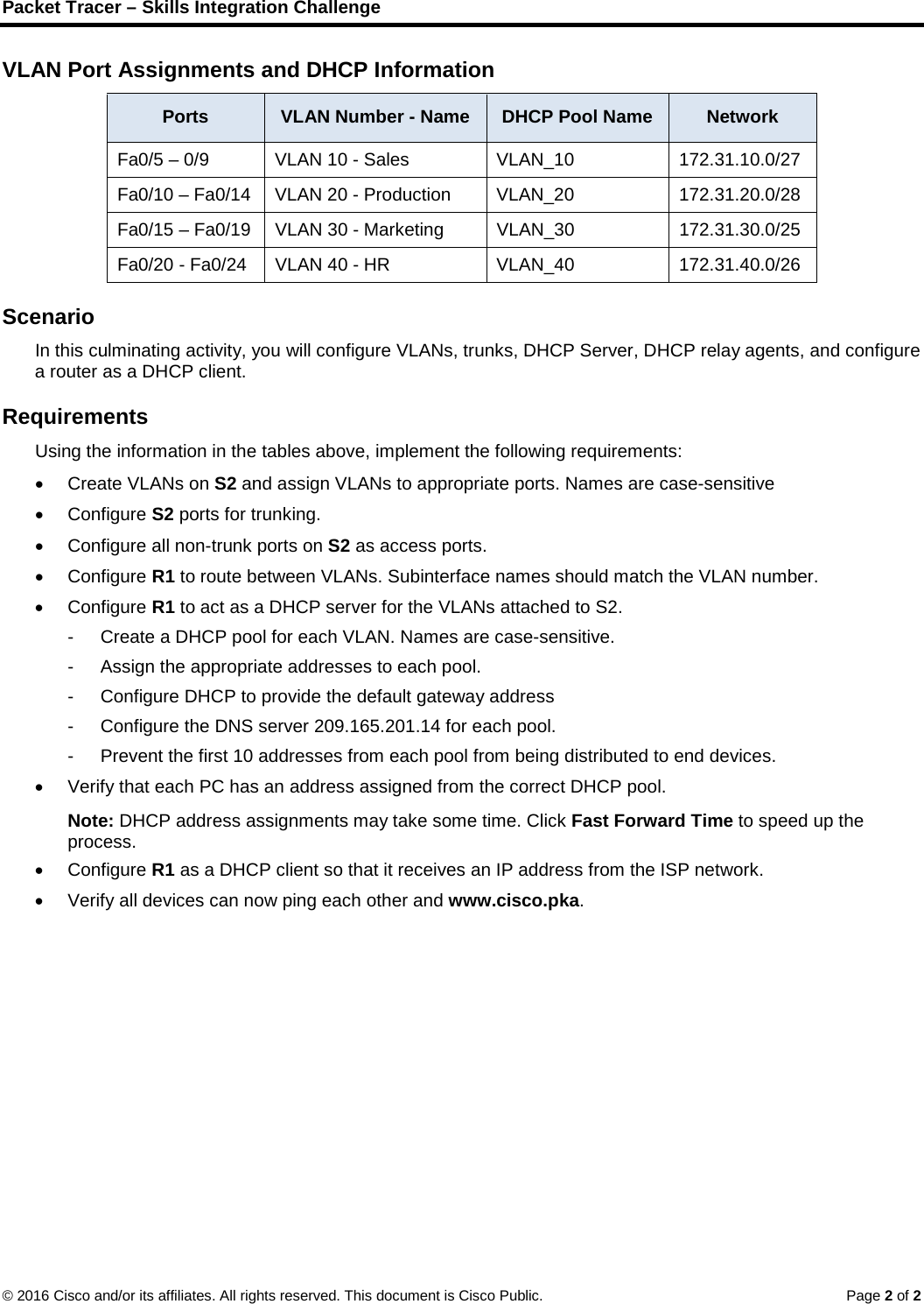
VLAN Port Assignments and DHCP Information
| Ports | VLAN Number – Name | DHCP Pool Name | Network |
| Fa0/5 – 0/9 | VLAN 10 – Sales | VLAN_10 | 172.31.10.0/27 |
| Fa0/10 – Fa0/14 | VLAN 20 – Production | VLAN_20 | 172.31.20.0/28 |
| Fa0/15 – Fa0/19 | VLAN 30 – Marketing | VLAN_30 | 172.31.30.0/25 |
| Fa0/20 – Fa0/24 | VLAN 40 – HR | VLAN_40 | 172.31.40.0/26 |
Scenario

In this culminating activity, you will configure VLANs, trunks, DHCP Server, DHCP relay agents, and configure a router as a DHCP client.
Requirements
Using the information in the tables above, implement the following requirements:
- Create VLANs on S2 and assign VLANs to appropriate ports. Names are case-sensitive
- Configure S2 ports for trunking.
- Configure all non-trunk ports on S2 as access ports.
- Configure R1 to route between VLANs. Subinterface names should match the VLAN number.
- Configure R1 to act as a DHCP server for the VLANs attached to S2.
- Create a DHCP pool for each VLAN. Names are case-sensitive.
- Assign the appropriate addresses to each pool.
- Configure DHCP to provide the default gateway address
- Configure the DNS server 209.165.201.14 for each pool.
- Prevent the first 10 addresses from each pool from being distributed to end devices.
- Verify that each PC has an address assigned from the correct DHCP pool.
- Note: DHCP address assignments may take some time. Click Fast Forward Time to speed up the process.
- Configure R1 as a DHCP client so that it receives an IP address from the ISP network.
- Verify all devices can now ping each other and www.cisco.pka.